Turbojet Engine Schematic Diagram. The bottom plate and the ring are welded to. Homemade Turbojet Engine: Attached is a documented process with instructions allowing reproduction of a turbo jet engine; primary construction materials include junkyard parts and scrap steel.

CONCLUSION Turbojet engines are more complex. Materials used should satisfy many engine criteria. Materials development should be with full acceleration. Some new technologies have to be developed in such a way that it should increase the engine performance and reduce life.
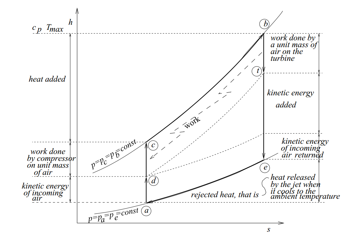
The influence that is brought to me by this picture is, pressure plays a large role in the process of propulsion.

Schematic diagram for non-afterburning turbojet engine. 1 ...

Schematic of two-spool separated-flow turbofan engine and ...

Turbojet Engine

4: Simplified schematic of a low by-pass fan jet engine ...

November 2013 Basic Training - Turbochargers: How They ...
TurboJET - TurboJET - JapaneseClass.jp

jet engine | Tiếng Anh Kỹ Thuật

New Brazing Alloys Improve Thermal Barrier in Jet Engine ...
These mind-blowing GIFs explain how a jet engine works ...
The compressor slows down the incoming air, raising its pressure, and. Turbojet Engine - Free download as PDF File (.pdf), Text File (.txt) or view presentation slides online. In the post-war years, researchers used the Jet Propulsion Static Laboratory (JPSL) to develop technologies to increase jet engine thrust.
